PREVIOUS
NO. 10
Skeletal Animation:
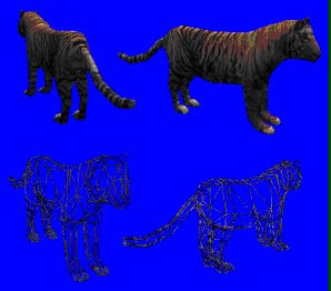
A 3D model is composed of hundreds or thousands of polygons of various shapes and sizes joined together form the shape desired. The number of sites has increased steadily so that now to form the arm of a particular model is used by thousands of polygons ... thousands of polygons that have to change their size and shape with every slight movement of the model. Calculate
each deformation of these thousands of polygons and their new coordinates in the scene, besides the application of light effects on them, textured, filtered ... The work required by the graphics system is tremendous. To eliminate that huge cargo base technology "skeleton 3d. The "skeletal animation is based on creating an architecture model or skeleton and then cover it texture (or skin). With this technique, each member of the gorilla sample covering polygon build a "bone" (bone) of the skeleton. The benefits come when that member has to move from the body. Each bone will have a limited movement with respect to the bone that joins with exactly the same way as it has the real animal. Each moving part of the model is formed through a bone that has its own coat of meat (polygons) and their own skin (textures) and the mobility that the programmer I want to give. Thus, the gorilla's example might have a bone that allows you to move the arm about the shoulder, forearm, the rest of the arm, hand on the forearm, fingers on the hand ... The movement is much more realistic and, above all, it requires far fewer system resources by not having to calculate the deformation of the polygons that until now were used to represent the joints.
The only problem of creating 3D models from a skeleton found at the junction of the various bones. Between a bone and another is a space that, according to the comparison with the actual body of vertebrates, called a joint. This joint contracts, it stretches and deforms in different ways depending on the movement to make the two bones that connects eg

The rift that develops between two bones is something that can not be displayed in the image final. To hide it using the technique "Skinning", as its name suggests, is responsible for skin EFG these imperfections. 
Through this flexible skin that connects each of the vertices of a corresponding bone in the other, giving continuity to the object and is very close to all-natural motion can be seen in any living being. A problem that generates this "skin" lies in the texture that covers the skin.
The problem is how to connect the various bones of the final look so realistic. That takes the Vertex Skinning. This technique is based on the application as realistic as possible the calculation of mathematical functions that calculate the position of each vertex of an object in the scene. Explained in a simple, takes care of filling the most realistic way possible gaps between the various "bones" of which we have spoken. The union between those bones is more real the more matrices are used. These matrices are mathematical calculations designed to connect together each vertex of the object. The more times you recalculate the union (more arrays there), more realistic the final object.

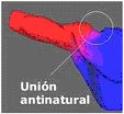
arm model (red) joins the torso (in blue). Each color represents one of the matrices and, as we see, the union between them is unnatural. ATi Radeon cards as supporting up to four arrays for hardware, so that examples like this, adding a third array would solve the problem.

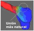
matrices include red and blue, has introduced a third matrix represented in green. This matrix is \u200b\u200binserted between the other two acting as a kind of flexible cushion that makes the union of two more natural. If the result is not the sought could introduce a fourth matrix and further improve the outcome. Another advantage of having more matrices in representing a model, is that you can define the behavior of the texture (skin) that covers each array. If it is to represent an animal's skin, the texture that covers the central matrix is \u200b\u200bstretched while covering the other two matrices remain the same. Similarly, each matrix may be affected differently by light, darkening or lightening the texture that covers it.
The great advantage of the ATI Radeon is calculated up to four of these matrices in hardware. Software to calculate these matrices would be impossible as the main processor would completely collapsed before this influx of calculation operations in real time.
The following chart we can see a real example in a game, Dungeon Siege from Microsoft, which you can see the four matrices in different colors.
Each color represents a matrix, however, more effective implementation of the different arrays, shown is more effective in automatic transitions. The familiar "morphs."
Formats:
. Fbx
FBX format developed by Kaydara to exchange information.
FBX is a binary format that supports all kinds of 3D data, 2D, video and audio, greatly facilitating communication between different applications (like Cinema4D, Lightwave, 3D Studio).
.
fpx format that supports multiple resolutions of an image. With or without compression and 8 to 24 bits of color depth Developed by Kodak in conjunction with Hewlett Packard
. X
files. X are composed of templates, which can be defined by the user. A template is a "definition of how the user wants to store the information."
To encourage a file. X need to specify a series of animations with reference to the corresponding frame matrices. Below is an example of our square textured and animated.
An example of these formats "optimized" for games are those used by Id Software for Quake. You may write a tutorial on this most adellante format, but for now let's start with a more simple format. X which is the default using DirectX.
there a tool that comes with the DirectX8 SDK to transform files formatted 3dStudio. X in C: \\ MSSDK \\ bin \\ DXUtils \\ XFiles \\ conv3ds.exe
these files. X will contain information about our 3D models (characters, ships, etc ...) and even our 3D world (tracks, cities, maps, etc ...)
key points when working with these files are:
- In what ways are stored objects.
- how they are interrelated.

Through this flexible skin that connects each of the vertices of a corresponding bone in the other, giving continuity to the object and is very close to all-natural motion can be seen in any living being. A problem that generates this "skin" lies in the texture that covers the skin.
The problem is how to connect the various bones of the final look so realistic. That takes the Vertex Skinning. This technique is based on the application as realistic as possible the calculation of mathematical functions that calculate the position of each vertex of an object in the scene. Explained in a simple, takes care of filling the most realistic way possible gaps between the various "bones" of which we have spoken. The union between those bones is more real the more matrices are used. These matrices are mathematical calculations designed to connect together each vertex of the object. The more times you recalculate the union (more arrays there), more realistic the final object.

arm model (red) joins the torso (in blue). Each color represents one of the matrices and, as we see, the union between them is unnatural. ATi Radeon cards as supporting up to four arrays for hardware, so that examples like this, adding a third array would solve the problem.


matrices include red and blue, has introduced a third matrix represented in green. This matrix is \u200b\u200binserted between the other two acting as a kind of flexible cushion that makes the union of two more natural. If the result is not the sought could introduce a fourth matrix and further improve the outcome. Another advantage of having more matrices in representing a model, is that you can define the behavior of the texture (skin) that covers each array. If it is to represent an animal's skin, the texture that covers the central matrix is \u200b\u200bstretched while covering the other two matrices remain the same. Similarly, each matrix may be affected differently by light, darkening or lightening the texture that covers it.
The great advantage of the ATI Radeon is calculated up to four of these matrices in hardware. Software to calculate these matrices would be impossible as the main processor would completely collapsed before this influx of calculation operations in real time.
The following chart we can see a real example in a game, Dungeon Siege from Microsoft, which you can see the four matrices in different colors.
Each color represents a matrix, however, more effective implementation of the different arrays, shown is more effective in automatic transitions. The familiar "morphs."
Formats:
. Fbx
FBX format developed by Kaydara to exchange information.
FBX is a binary format that supports all kinds of 3D data, 2D, video and audio, greatly facilitating communication between different applications (like Cinema4D, Lightwave, 3D Studio).
.
fpx format that supports multiple resolutions of an image. With or without compression and 8 to 24 bits of color depth Developed by Kodak in conjunction with Hewlett Packard
. X
files. X are composed of templates, which can be defined by the user. A template is a "definition of how the user wants to store the information."
To encourage a file. X need to specify a series of animations with reference to the corresponding frame matrices. Below is an example of our square textured and animated.
An example of these formats "optimized" for games are those used by Id Software for Quake. You may write a tutorial on this most adellante format, but for now let's start with a more simple format. X which is the default using DirectX.
there a tool that comes with the DirectX8 SDK to transform files formatted 3dStudio. X in C: \\ MSSDK \\ bin \\ DXUtils \\ XFiles \\ conv3ds.exe
these files. X will contain information about our 3D models (characters, ships, etc ...) and even our 3D world (tracks, cities, maps, etc ...)
key points when working with these files are:
- In what ways are stored objects.
- how they are interrelated.

MODEL:


 4 .- Invetige about texture mapping in OpenGL